
APF
HIGH PRESSURE GEAR PUMPS
APF pumps are volumetric gear pumps suitable for transferring lubricant viscous liquids without any suspended solids or abrasive substances. They are self-priming pumps used for a wide range of liquids with a viscosity from 1 to 1000 cSt (when driven by a standard industrial electric motor). The speed of rotation is chosen according to the viscosity of the liquid. Flowrate range is from 5 to 80 L/min. These pumps are designed to reach a maximum pressure of 25 bar.
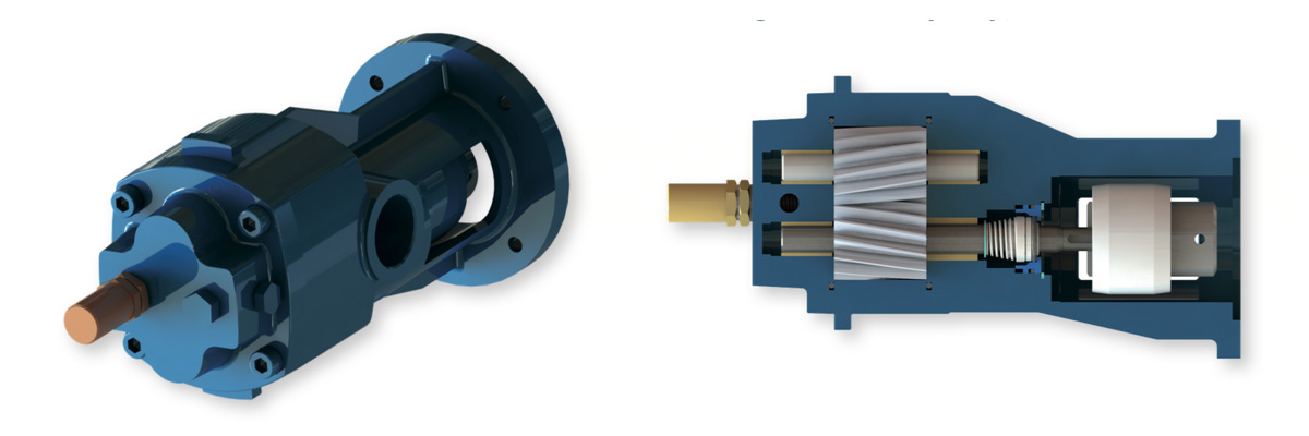
The standard construction consists of pump housing and cover in cast iron, shafts and gears in carbon steel, APF are bare shaft pumps designed to be coupled to an IEC electric motor IMB34 by means of coupling.
O-rings in Viton, sleeve bushings in sintered bronze and mechanical seal in ceramic-graphite-Viton. APF pumps are supplied with a pressure relief valve in brass. Nozzles in inlet and outlet are of the same diameter and positioned on the same axis.
A short and straight alignment of the flow channels provides for a good suction capability and a quiet running. The helical gears result in extremely low noise levels and reduced pressure pulsation.
Nozzles in inlet and outlet are of the same diameter and positioned on the same axis.
A short and straight alignment of the flow channels provides for a good suction capability and a quiet running. The helical gears result in extremely low noise levels and reduced pressure pulsation.
APF are bare shaft pumps designed to be coupled to an IEC electric motor IMB34 by means of coupling.
The electric motor can be supplied on request. Standard flanges are listed as follows:
Nominal flow rates

Table 302 shows the possible flow rates for non-pressurized speed. The selected speeds are the most common speeds pumping (Δp=0) and a 46 cSt fluid. at rated power of industrial electric motors at 50 and 60Hz. The flow rate of gear pumps is virtually proportional to their
SENSE OF ROTATION AND FLOW DIRECTION

The standard version of APF pumps can operate only in one direction of rotation: counterclockwise watching the pump shaft end.
The direction of the fluid flow is shown by an arrow placed nearby the piping connections.
A proper mounting will keep the nameplate on the top side. In this case the flow direction will be from the left side to the right side watching the pump shaft end and the pressure side (delivery) will be at the right-hand side.
On request a clockwise version can be supplied.
Overal dimensions and weights

